9 Results
View results:
Sort by:
LVL
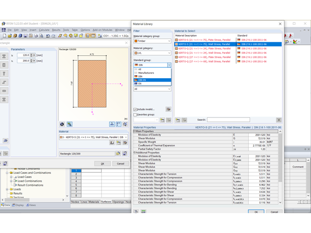
Can I design laminated veneer lumber with RFEM 5 or RSTAB 8?
Question
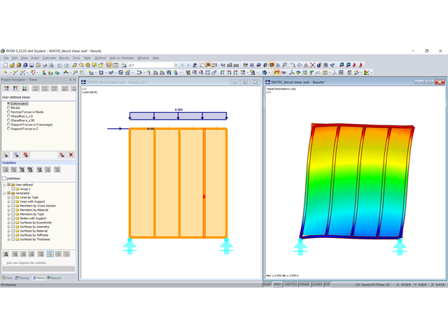
How can I model a timber panel wall with RFEM?
Question
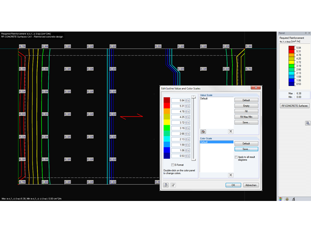
Is it possible to freely define the numerical values of isoline intervals (for example, result display of the isolines for the bottom reinforcement as1 in steps of 5.0 cm²/m)?

Question
How can I enter the earth covering of a bucket foundation up to 10 cm below the top edge of the bucket in RF‑/FOUNDATION Pro?
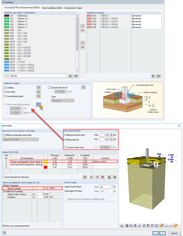
Question
How do I activate the earth covering (permanent)? The corresponding check box is deactivated.
Question
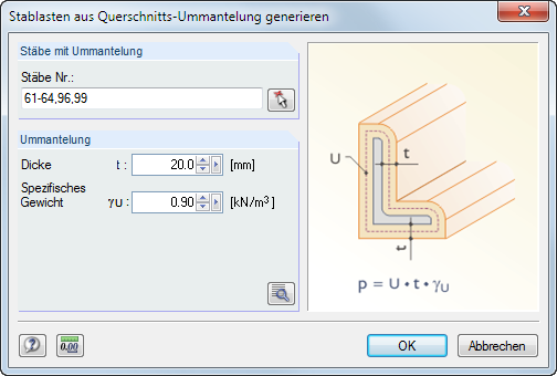
Can the loads from coating, for example, from covering of a member or icing, also be generated for a cross-section?
Question
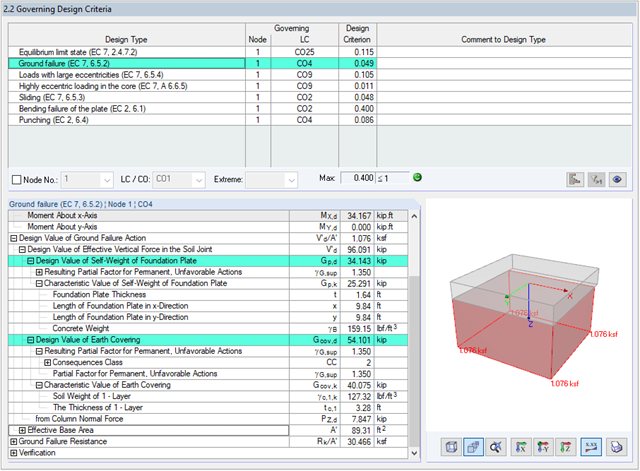
How can I find out how the self-weight of a foundation plate or any imposed load on the foundation plate is considered in the design checks?
Question
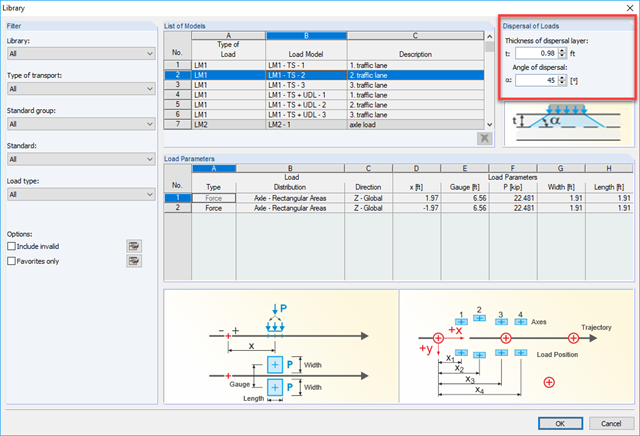
Can I enter an earth covering in RF-MOVE Surfaces through which the load distribution width of concentrated loads is automatically taken into account?
